


Conveyor Roller Design: How to Create a Better, More Efficient Roller
The manufacturing industry isn’t showing signs of slowing down. A recent look at the U.S. consumption of cutting tools shows a 10% increase year-to-date, along with an increase in machine tool orders. There are growing demands in industries that provide digital printing, packaging, photographic, glass, processing and converting equipment, in addition to the mining, aerospace and transportation fields.
Technology is moving at lightning speeds. So why use older manufacturing techniques?
Whether you are tasked with finding replacement rollers, designing a system from scratch for a new space (or attempting to reconfigure an existing conveyor system to improve efficiency), you should familiarize yourself with the alternatives available in roller design.
First, a quick review of the three most common traditional conveyor roller manufacturing methods:
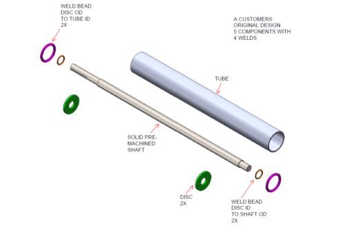
Solid Thru-Shaft
The design for solid thru-shaft rollers entail machining the shaft, machining the discs, manually welding the discs to the shaft, and then manually welding the shaft once it’s been positioned in the tube.

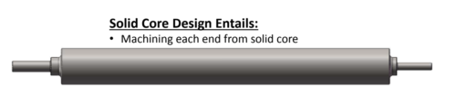
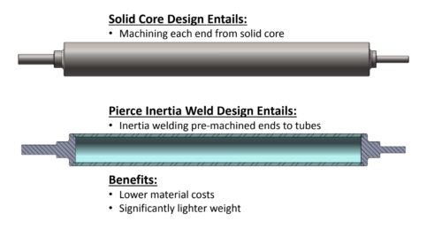
Solid Core
As implied, these rollers are machined at each end of a solid core.
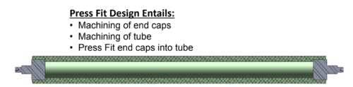
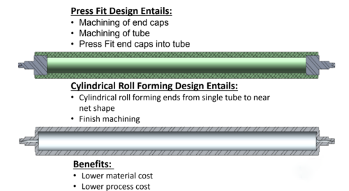
Press-Fit
A press-fit design requires the machining of end caps and the tube, then press-fitting the end caps into the tube.
Design a better roller using these 2 innovative techniques:
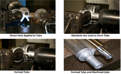
Cylindrical Roll Forming
In this unique process, a rotating tube is heated using direct heat. Once the tube reaches the specified temperature, CNC controlled forming mandrels produce the desired ‘neck’ section, or, completely seal the end of the tube to provide an airtight enclosure. This process produces a near net shape to the finished product, significantly reducing the amount of raw material and additional machining requirements.
Immediately one can see that cylindrical roll forming minimizes waste as it involves only one piece of material. The forming process is also much faster as no multiple parts to join, plus it forms to near finish spec. A design plus is that there is a large variety of wall thicknesses and shapes that can be obtained, not to mention that it can be performed on a range of wall thicknesses and metals that are available in tubular shape.
Press-fit Method vs Cylindrical Roll Form
Inertia Friction Welding
During the inertia friction welding process, a rotating part is pressed against a separate component that is held stationary. The heat created by the friction allows the metals to flow, and creates a robust bond at the weld interface.
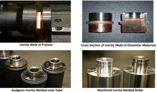
Inertia friction welding offers a major reduction in manufacturing costs — an attractive option when designing rollers. This offers the freedom to only use expensive materials where absolutely essential, without sacrificing quality, as the the bond formed between the dissimilar metals maintain material strength.
It also frees up cycle and labor times: IFW bonds pieces that are already sized to near final dimensions and is up to 10x faster than MIG or TIG welding. As a machine-controlled process, one can factor in repeatability with consistent results.
Solid Thru-Shaft Method vs Inertia Friction Welding
The Futian advantage:
Futian Industries is a leader in industrial roller core manufacturing and pioneer the two innovative processes described above. We specialize in providing custom manufacturing solutions with a focused effort in reducing production time and material cost.
Let’s work together on your next design project. Schedule an engineering consultation with us today.